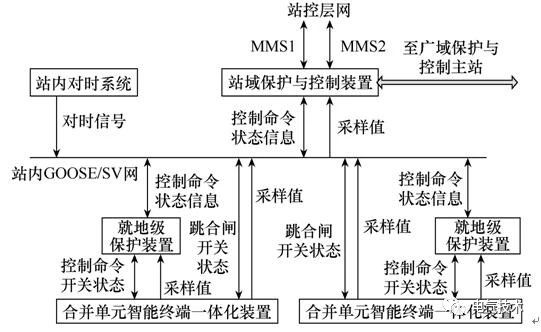
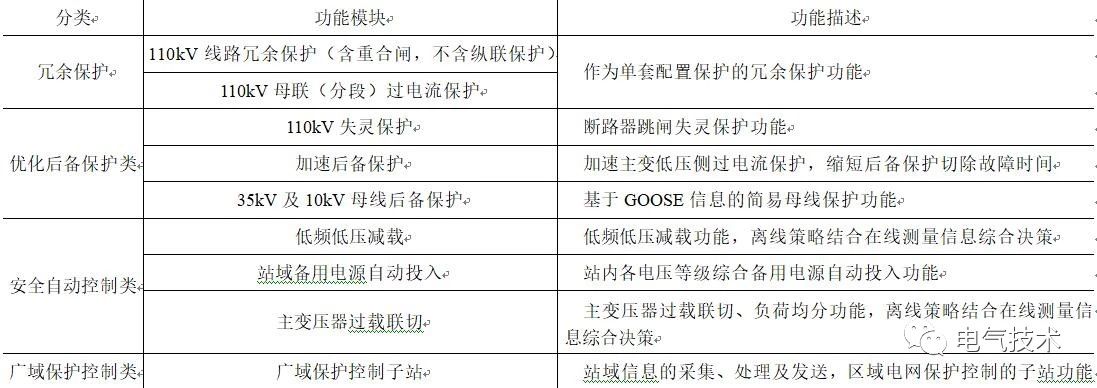
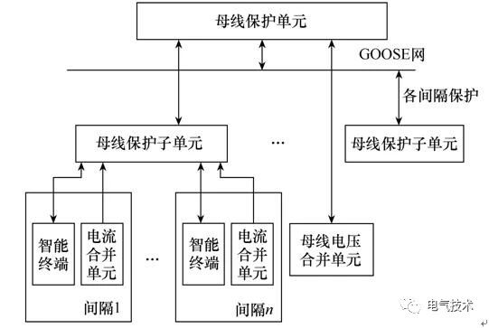
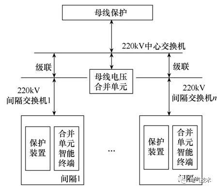
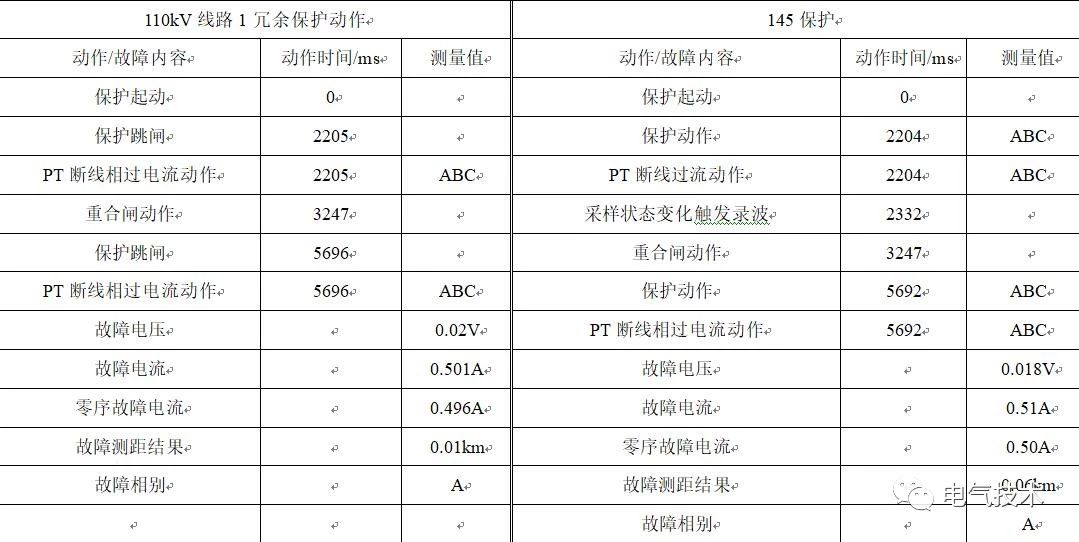
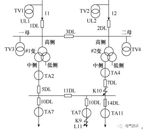
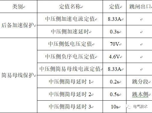
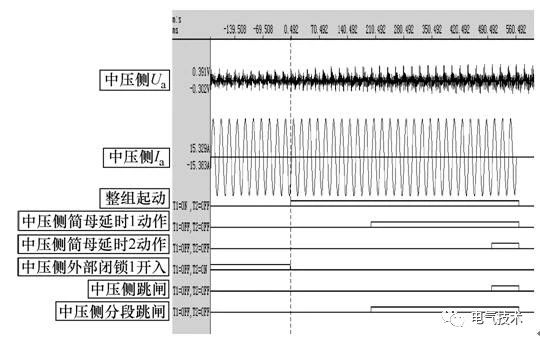
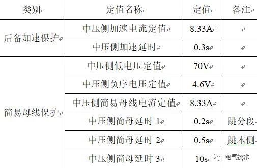
In order to be able to better analyze the difference between the new generation of smart substation station protection and conventional relay protection, this article describes the research status, functional configuration and functional principles of the station domain protection based on the field test of a 110kV. Line redundancy protection and performance of low redundant backup protection are analyzed. The results show that a new generation of smart substation station protection can better protect the secondary system. In recent years, with the rapid coordinated development of China's power grids with UHV as the backbone grid, a smart grid featuring information, automation, and interaction has gradually emerged [1]. As the first line of defense for the safe and stable operation of power grids, relay protection must adapt to even the development needs of the grid [2]. Compared with traditional smart substations, the new generation of smart substations adopts a hierarchical protection control system, which is mainly composed of three levels: local level protection control [3], station-level protection control, and wide-area level protection control [4]. The station-level protection control is for a single protected object, utilizes information such as electrical quantity, switching quantity, and state-of-the-art equipment protection status of multiple objects within the station, centralizes decision making, realizes redundancy and optimization of protection, and completes and upgrades the level of substations. Safe automatic control function can also be used as a substation for wide area protection control. As a key part of the hierarchical protection system, the station protection and control system makes comprehensive use of the electrical quantity and switching information of the multi-interval lines and components in the station, which can not only achieve the fast, accurate and reliable isolation of the fault point, but also realize the redundancy within the station. Backup protection, optimized backup protection and automatic security control [5]. The station protection control can obtain multiple intervals or total station information, more information than the interval protection, and can supplement and optimize the existing protection system. For systems with 110kV and below voltage ratings that do not have dual protection devices, centralized redundancy protection can be performed, and functions such as full station standby investment, low-frequency and low-voltage load shedding devices, and breaker failure protection can be realized. Based on the analysis of the research status and system principle of station protection, this paper analyzes the site redundancy protection and low redundancy backup protection of a 110kV line in Yuncheng City, and compares and analyzes the protection of the station and the conventional microcomputer. Differences in the characteristics of electrical protection. The results show that a new generation of smart substation station protection system can effectively detect and control the fault and improve the reliability of the protection. 1 Research status of station protection At present, the protection methods of the station domain are mainly divided into centralized (integrated) protection and distributed (networked) protection. [6] proposes a centralized protection using two-layer configuration scheme logically, ie, a unit protection module based on differential protection is used as a gap-level protection, and a network protection module based on topology theory is used as a system level of the entire station. protection. Literature [7-8] proposed a digital centralized protection device that uses a unified software and hardware platform and configures protection, measurement, and control functions. Literature [9] proposed a digital integrated protection and control system DIPC based on the multifunctional protection controller MPCU. Literature [10-12] designed an integrated protection prototype for 110kV digital substations, studied the improvement of integrated protection for traditional line protection, transformer protection and other functions, and conducted real-time sampling, data synchronization, and reliable transmission of process-level network communication systems. Correlative analysis was done. The literature [13] defines the distributed networked protection in the smart substation and points out its application scope, ie implementing distributed bus protection on the protection, and achieving networked self-powered and low-frequency and low-voltage load shedding on the control. The literature [14] proposed a non-master distributed bus protection scheme. Each bus-interval protection unit interacts with data through a highly reliable ring network. When a fault occurs, the corresponding circuit needs to be disconnected without causing any trouble. The entire bus is out of power. 2 Next-Generation Station Domain Protection Configuration The station domain protection and control device is based on the data sharing of the process level network of the smart substation, receives electrical sampling data (network mining) through the network, and issues control commands (web hopping) such as tripping and closing. The position and external information exchange of the station protection and control device in the smart substation is shown in Fig. 1. It collects the information data of the entire station process layer and station control layer network, and completes the redundant backup, optimized backup and backup at the local level. Safe and automatic control, at the same time with independent communication interface, support wide-area communication, complete the substation function of the wide-area protection control system. Fig. 1 Station area protection and control device The function configuration of the station domain protection and control device in the new generation of smart substations mainly includes the substation functions of redundancy protection, optimized backup protection, security automatic control and wide area protection control. From the function configuration table in Table 1, it can be found that the redundancy protection in the station domain protection only includes redundancy for a single set of configuration protection. If the primary change protection has been configured in duplicate, then redundancy should not be configured in the station domain protection and control device. The redundancy protection function in the station area protection and control device does not include the line pilot protection. The main reasons are: 1 channel and the opposite side equipment do not support, if need to support, need to increase a large number of equipment and engineering quantities; 2 if including the line longitudinal joint Protection, the station domain protection will be associated with multiple stations through the line, greatly increasing the complexity and impact range. There is no need to include redundancy of 10kV interval protection in the station protection and control device. The main reason is that traditional transformers and “lliu one†devices are used at intervals of 10kV, and there is no independent merging unit and intelligent terminal. If the station protection device achieves 10kV Interval protection, then its sampling and exports also have to go through the "all-in-one" device, "all-in-one" device out of operation for some reason, the station area protection will not be redundant. Table 1 Function Configuration Table of Station Domain Protection 3 station domain protection principle 3.1 Sampling and tripping methods Whether in smart substations or conventional substations, on-site protection devices use straight-through production methods, while the station protection rate first uses the network-picking network jump method to work. Since this article focuses on the protection methods in smart substations, it compares the direct production jump and net mining jump in smart substations. 1) Straight-through production refers to the transmission of sampled values ​​and the tripping and closing signal directly through point-to-point connection between intelligent electronic devices without using a switch. The working principle is shown in Figure 2. The advantage of this method is that the protection device does not rely on the external timing system to achieve its protection function, and avoid the delay of the sampling and tripping information uncertainty caused by the switch in the networking mode. The disadvantage is that there are many optical ports of the protection device, which makes the secondary circuit optical fiber connection complicated. Figure 2 straight mining work principle diagram 2) Net mining The network jump refers to the way the intelligent electronic equipment exchanges sampling values, transmits, and closes and switches signals through the switch. By dividing VLANs to avoid excessive information flow, its operating principle is shown in Figure 3. The advantage of this method is that the protection device realizes signal input and output through the network, effectively reduces the number of optical ports of the inter-spacing protection device such as bus protection and main transformer protection, and simplifies the secondary circuit optical fiber connection. The disadvantage is that multi-interval data synchronization relies on the time-dependent system and network, and there is a delay in the networked information exchange. 3.2 110kV line redundancy protection 110kV line local level protection generally single set configuration, when the protection out of operation for any reason, 110kV line will lose protection. Therefore, 110kV line protection is configured in the station protection and control device as redundancy at the local level. However, due to the limitations of the communication channel, the line protection in the station domain protection does not consider longitudinal protection, and other protection functions such as distance protection, zero-sequence over-current, reclosing, and manual acceleration are consistent with the local-level line protection. Figure 3 Networking hops working principle 3.3 Transformer Backup Protection When the 220kV and above systems are designed, the localized transformer protection is configured according to the principle of dual integration of the main and the rear. Any set of transformer protection will exit the operation for any reason and will not affect the operation of the transformer. In-situ transformer protection for 110kV and below systems is in accordance with the dual-configuration of the main and the rear, or the protection configuration after the main and rear separation, and any set of protection equipment will exit without affecting the operation of the transformer. Based on the above reasons and the information sharing and cooperative protection technology between stations, the protection of the station area complements the backup protection of the transformer and enhances the backup protection performance of the transformer through the locking and acceleration protection of the adjacent bay protection. The backup overcurrent protection operation on the low-voltage side of the transformer cuts out the fault and the operation delay is long, causing damage to the primary device. The use of simple bus protection can quickly cut off the fault to reduce the damage of transformer substation low-voltage bus short-circuit fault to switch cabinet and transformer. In the case of faults outside the bus zone, related protections such as low-voltage side outlets can send signals to block simple busbar protection; in case of bus zone faults, low-voltage side outlets and other related protections do not issue blocking signals, and simple busbar protection can quickly remove transformer low-voltage side circuit breakers. If there is a small power supply on the low-voltage side, when the bus zone is faulty, the simple bus protection trips the small power supply on the low-voltage side after a delay, and then the low-voltage side breaker is tripped by the delay. The simple bus protection is taken from the bus TV and can realize compound voltage blocking (low voltage, negative sequence voltage). The current is taken from the three-phase TA of the transformer low-voltage side breaker. The simple bus protection is compound voltage blocking over-current protection. 4 site protection field analysis In order to compare and analyze the performance differences between the new-generation station domain protection and the traditional microprocessor-based relay protection, this paper uses the 110kV line redundancy protection and the transformer medium-voltage side redundant backup protection as examples. 4.1 110kV Line Redundancy Protection Case Take the 110 kV East Central Line 145 as an example. In the setting calculation, the 110 kV line 1 redundant protection setting is exactly the same as the 145 line-level line protection setting. Both sets of protection are put into operation. Under the same operating conditions, the comparison After the coincidence of the two, the protective action behavior is accelerated under the circumstances. Because it is impossible to directly input current to the electronic transformer, only by performing the up-flow test on the primary device to simulate the fault condition in the line, the possibility of implementing the line redundancy protection is verified through the overcurrent protection of the PT disconnection phase. The overcurrent setting of the PT disconnection phase is 0.4A and the time is 0.2s. See Table 2 for the comparison of the entire protection operation report. Comparing the two actions, the station protection 110kV redundancy protection is only 1ms later than the 145-level line protection action, and the operation behavior is correct. However, under the same fault voltage, the fault current of the station protection is 0.51A, zero. Sequential fault current is 0.50A, which is much smaller than the 120.27A fault current and 119.14A zero-sequence fault current. And the fault location is more accurate. It can be seen that 110kV redundancy protection has the response speed of line protection and can be used as backup protection for 110kV line protection. The operation value, operation time and action logic are in line with the State Grid Corporation's corporate standard GDW 11053-2013 "Regulations for inspection and protection control system of station area" The requirements for simple busbar protection are as follows: The allowable operating value error is not more than ±5% or ±0.02IN, and the allowable delay error is not greater than ±1 or ±40ms. Table 2 comparison report of protection actions 4.2 Transformer Medium Voltage Side Redundant Backup Protection The simple busbar protection voltage is taken from the bus TV and can realize compound voltage blocking (low voltage, negative sequence voltage). The current is taken from the transformer's medium-voltage and low-voltage side circuit breaker three-phase TA. The simple bus protection is compound voltage blocking overcurrent protection. Figure 4 shows the schematic diagram of the simple bus protection main wiring. The following takes the fault point in the schematic diagram shown in Fig. 4 as an example to analyze the medium voltage side fault and the medium voltage side circuit fault of the main transformer. 1) Failure of medium-voltage side branch K1 of No. 2 main transformer When the No. 2 main transformer medium-voltage side branch K1 fails, the fault current detected at TA4 exceeds the simple bus protection setting, and there is no external line protection blocking condition. The simple bus protection action outlet trips the branch 4DL. In order to verify the reliability of the simple bus protection operation, this paper simulates the medium voltage side fault of the main transformer in the substation, and the setting of the simple bus of the medium voltage side of the main transformer No. 2 is shown in Table 3. Figure 4 Simple bus protection main wiring diagram Table 3 No. 2 main transformer medium bus side simple bus fixed value Change the No. 2 medium-voltage side 342 switch (4DL) and the medium-voltage side section 340 switch (11DL), and input the fault current to the No. 1 main transformer medium-voltage side merging unit. Input, so set the fault time to 550ms. The analysis of protection waveforms in the station domain using the analysis software of Zhongyuan Huadian CAPP2008 is shown in Figure 5. Figure 5 bus protection operation and recording waveform From Fig. 5, it can be seen that the whole bus protection group starts at 0ms, the 199.5ms station domain protection No. 2 main transformer medium pressure side SIMB delay 1 action, and the No. 1 main transformer side BPF side section 340 switch; 499.5ms. On the medium-pressure side, the simple master delay 2 action, jump open the No. 1 main transformer medium pressure side 341 switch, action value, action time, action logic in line with the requirements of the enterprise bus standard for simple bus protection. 2) Fault at K2 in L1 of main transformer outlet No. 2 When there is a fault at K2 at L1 of medium-voltage side outlet of No. 2 main transformer, due to the line protection device at 6DL, the over-current protection start signal is sent to the station domain protection device to block the No. 2 main transformer bus protection by GOOSE protection. 2 No. Bus change bus protection is blocked and reliable does not move. This article simulates a line fault condition with 35kV line switch quantile and position. Table 4 Fixed value of simple bus protection in medium voltage side Table 5 3405 protection settings for 35kV lines (1) When the 35kV line switch is in the quintile A 8.75A fault current is applied to the medium voltage side 342 switch of the main transformer No. 2 and the 3405 switch of the 35kV circuit, and the fault duration is 700ms. The operation situation and fault recording are shown in Figure 6. 0 Full group start, 14.5ms external latch 1 open (3405 protection start GOOSE signal associated with the protection of the medium-side side of the external block 1), 15ms the entire group start, the external lock signal continues until the fault disappears. Figure 6 3405 simple bus protection operation and waveform recording (276) It can be seen from Figure 6 that when the 3405 line fails, the entire group of 3405 protection devices starts protection, and 3405 protection opens the external blocking signal to the station area protection, thereby blocking the simple bus protection of the medium voltage side of the No. 2 main transformer until the fault disappears. There will be no accident that the entire busbar trips due to a line fault. (2) When the 35kV line switch is in the closed position The fixed value remains unchanged, the 3405 switch is closed, and its action behavior and waveform recorded as shown in Figure 7. Figure 7 Simple bus protection operation and waveform recording (473) 3405 protection device action, jump 3405 switch, at the same time sent to the station domain protection GOOSE lock command, but the protection action can only block the station domain protection 200ms, if the fault has not been removed after 200ms, then the station domain protection group start, due to The fault has not ended yet, so the short delay 1 action trips the mid-section switch. 5 Conclusion The research results of this paper have been successfully applied to a new generation of smart substations in Shanxi Province, innovating the relay protection mode of smart substations, realizing the transition from component-oriented to system-oriented, and changing from object-oriented to function-oriented, improving the reliability, sensitivity and choice of protection. Sex. The following conclusions were obtained through the study. 1) This paper mainly analyzes the performance of 110kV line redundant protection and reduced redundant backup protection. The experimental results show that the new generation of smart substation station protection can better protect the secondary system. 2) The station domain protection control device compensates for the lack of local-level protection and makes the protection and control functions of the power system more complete. The promotion and application of the station area protection and control device is expected to further improve the safe and stable operation level of smart substations and power grids, with significant economic and social benefits. 3) The station-domain protection and control device can collect the information of the analog and digital switches of the entire station, identify the topology of the substation, and adopt appropriate algorithms and control strategies to further improve its protection performance.
Well Known Brand Compressor
¨ Unit adopts Germany BITZER or Taiwan HANBELL brand semi-hermetic screw compressor. The latest 5 to 6 patented screw rotor profile with excellent efficiency.
¨ Adjustable infinite or closely stepped capacity control, features energy efficient, stable and quiet running.
¨ Most advanced patented highest precision manufacturing process.
¨ Built-in full intelligent monitoring and protection including thermal motor temperature monitoring, phase sequence monitoring, manual reset lock-out, oil temperature sensor.
¨ Wide range of refrigerant for option, including R134a, R407c and R22(R404a, R507c upon request).
Microprogramming Control System
¨ Industrial PLC centralized control combined with compressor capacity control system, precisely monitor.
¨ Integrated protection for low temperature, high/low pressure, anti-freezing, phase missing, anti-phase, overload, motor over temperature, oil differential, flow switch, start up latency.
¨ Optional operation language, menu leading, unit running state easy to adjust.
Easy Installation, Reliable Running
¨ Closely stepped start-up, minimize impact to electricity.
¨ Steady and safe running, low vibration, easy for installation.
¨ Compact structure, less space demand and light in weight, easy for transport and installation.
¨ Completely wired, inspected and tested pre-delivery, saving installation time and cost.
Design Features
¨ W shape aluminum fin type condenser, assuring adequate heat exchanging area within smaller unit size
¨ High efficient evaporator with internal thread copper tube.
¨ Large air volume axial fan with metal blades. Motor separated from net-cover, fixed on exhaust port by metal
¨ Siemens PLC control, LCD touch screen interface.
¨ Standard design charged R22, CFC Free R407C, R410A,R404A,R134A for option.
¨ 380V-415V/50HZ 3PH for standard design. Different design on customers' request.
Air Cooled Screw Chiller,Air-Cooled Screw Refrigeration Unit,Explosion-Proof Screw Chiller,Air-Cooled Screw Split Chiller Shenzhen city KayDeli Refrigeration Equipment Co.,Ltd. , https://www.kaydelichiller.com