Roof Ridge Cap Roll Forming Machine, Roofing Roll Forming Machine, Roof Ridge Cap Roll Forming Machine Price, Ridge Cap Roll Forming Machine, Ridge Cap Machine
This kind of roof tile forming machine is specially desighed for making ridge cap tiles. It is very welcomed modern building material with better anti-bending performance. Its length can be set according to customer's requirements and transportation situation. Its color is selected from the color code of the steel factory.
Roof Ridge Cap Roll Forming Machine Roof Ridge Cap Roll Forming Machine, Roofing Roll Forming Machine, Roof Ridge Cap Roll Forming Machine Price, Ridge Cap Roll Forming Machine, Ridge Cap Machine Botou Xianfa Roll Forming Machine Factory , https://www.rollforming.nl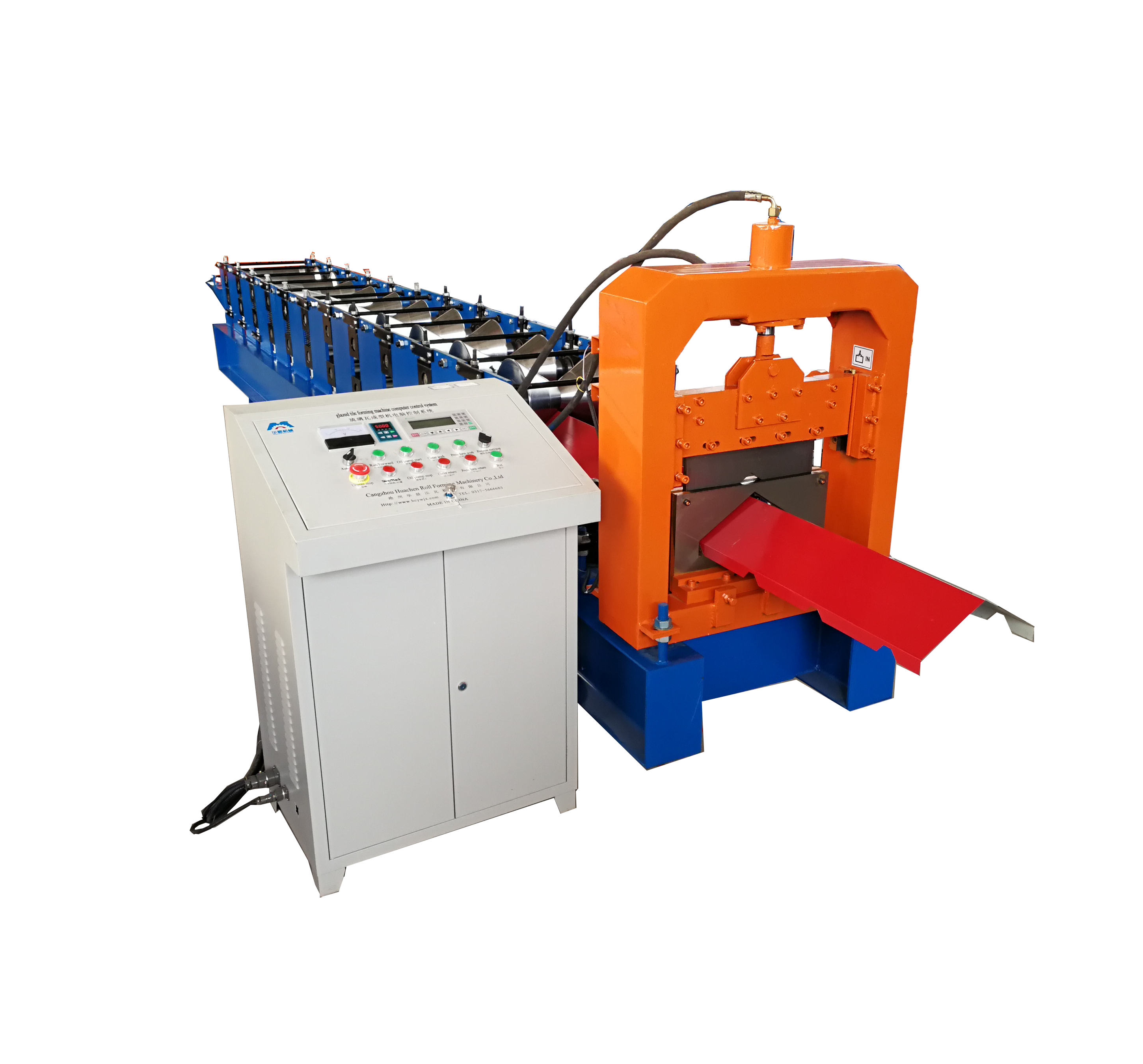
The adjusting mechanism is a device that converts the change of the output displacement of the actuator into the change of the circulation area between the valve spool and the valve seat of the control valve. Regulators are often referred to as valves, such as through single seat valves, angle valves and the like. Its structural features can be analyzed from the following aspects. From the structure of view, the regulatory agencies by the valve body, valve trim, valve cover assembly, the valve cover and other components. The valve body is a device through which the controlled fluid flows to connect the pipe to the fluid path and provide support for the valve trim and other trim. Valve trim is a component that comes into direct contact with the controlled medium inside the valve, including the valve plug, seat, stem, guide sleeve, sleeve, seal ring and so on. Normally, the upper bonnet assembly includes an upper bonnet, packing chamber, packing, upper deck and connecting bolts. In some regulatory agencies under the bonnet as part of the valve body, not separated. Lower bonnet for the end of the guide with the adjustment mechanism, which includes the lower bonnet, guide sleeve and drain screws and so on. For ease of installation and maintenance, the upper bonnet of some adjustment mechanisms is integral with the valve body, while the lower bonnet is separate from the valve body and is known as a separate body valve, such as some high pressure valves and body separation valves. From the body structure, can be divided into a valve seat and a valve seat with a single seat valve body, with two valve seats and a valve seat valve body with a connecting population and a connecting outlet The valve body has a three-way valve body with three connections (split of one population and two outlets or confluence of two and one outlet). Displacement from the spool to see, the adjustment mechanism is divided into linear displacement valve and angular displacement valve. They are used in conjunction with linear displacement actuators and angular displacement actuators, respectively. Straight-through valves, angle valves, sleeve valves, etc. belong to the linear displacement valve, also known as sliding stem valve (SlidingStemValve) o butterfly valve, eccentric rotary valve, ball valve, etc. belong to the angular displacement valve, also known as rotary valve (Ro-taryValve) o In recent years, some manufacturers have introduced mobile seat control valves that cooperate with the rotary actuators but still see linear displacements in terms of their relative displacement, such as Nufflo control valves. From the spool-oriented look, can be divided into top-oriented, top and bottom guide, · sleeve-oriented, stem-oriented and seat-oriented and other types. For fluid control and shut-off, etc., the guide of the valve core is very important, the valve guide is used for the centering of the valve plug and the valve seat. The top guide adopts a guide sleeve or packing structure in the valve cover or the valve body to realize the guide; the top and bottom guide adopts the guide sleeve of the valve cover and the lower valve cover to realize the guide, and the guide of the seat valve and the precise guide need to adopt the top and bottom guide ; The sleeve guide uses the outer surface of the valve core and the inner surface of the sleeve to guide, this guide has a self-aligning performance, can accurately align the valve core and the valve seat; The guide sleeve is centered on the seat ring and is guided by the sleeve and stem. The seat guide is used in the low flow control valve and is centered directly on the seat. From the unbalanced force suffered by the spool, the regulating mechanism of the valve unbalance and balance of two types. Balanced spool is the valve core open balance valve hole, when the valve spool moves, the valve core, the lower part of the hole due to the balance connection, therefore, most of the pressure difference between the two sides is offset, greatly reduced Unbalanced force on the role of the spool, balanced spool need to balance the chamber, therefore, need to seal the seal. Depending on the direction of flow, the pressure applied to the balance spool can be either the pressure upstream of the valve (center-to-center flow) or the pressure downstream of the valve (outside flow to the center). Balanced spools are available for sleeve-type spools and plunger-structured spools. Both sides of the unbalanced spool are the pressure before and after the control valve, therefore, the spool suffered unbalanced force, the same caliber control valve requires a larger thrust of the actuator can operate. Pressure drop from the spool to see, the spool structure has a single step-down and multi-stage buck points. Single-stage buck structure due to the pressure difference between the two ends, therefore, suitable for small noise, cavitation is not serious occasions. Demanding high noise, cavitation serious occasions. In the multistage buck structure, the pressure difference across the control valve is broken down into several differential pressure so that the pressure difference at each stage is small, cavitation and flashing will not occur, thereby preventing cavitation and flash evaporation Health, but also greatly reduce the noise. From the flow characteristics of view, according to the different changes in circulation area, can be divided into linear special, equal percentage characteristics, fast opening characteristics, parabolic characteristics, hyperbola characteristics and some correction characteristics. Flow rate, J Pi said stem displacement and fluid flow between the relationship. Normally, the flow characteristics are used to compensate for the non-linearity of the controlled object. The shape of the spool or the bore shape of the sleeve determines the flow characteristics of the control valve. Straight, the valve spool can be divided into flat type (for quick opening), plunger type, window type and sleeve type. As the opening area changes in different spool movement, the circulation area is also different, in order to achieve the desired flow characteristics. Plunger valves and window valves can also have different shapes depending on the desired flow characteristics. For example, traditional valve plates for butterfly valves, dynamic profiled valve plates, O-shaped openings for ball valves, V-shaped openings, modified openings and the like. Fast open linear percentage Figure 1 sleeve diagram of three commonly used sleeve control valve In view of the interchangeability of the valve trim, the trim of some adjustment mechanism can be easily replaced and maintained, for example, the sleeve valve can be conveniently Replace the sleeve to achieve different flow characteristics; top-bottom-oriented valve trim can be easily flip spool and valve seat to achieve the replacement of the body valve and the anti-body valve, so as to achieve the gas open and gas off the way to change; body separation valve Easy to disassemble for seat replacement and cleaning. From the bonnet structure, according to different application requirements, you can use ordinary bonnet, but also can use long-necked bonnet or with long neck cooling or heat sink bonnet, bellows sealed bonnet. Long-necked bonnet for high temperature and low temperature applications, the protection of stem packing, so that the medium temperature, to prevent bonding, biting card, leakage or reduce lubrication. In addition to the long bonnet bonnet, which extends the valve bonnet to keep the temperature of the packing away from the media operating temperature, a heat sink or heat sink can be added to create a long neck bonnet with heat sink or heat sink to allow the media temperature Get lower or higher. Typically, cast long neck bonnets have good heat dissipation and high temperature flexibility and are used in high temperature applications; stainless steel long bonnet bonnets have lower thermal conductivity and better low temperature adaptation Sex, is used for low temperature applications. When the controlled medium is not allowed to leak, you can not use the common filler structure on the bonnet, bellows must be used on the bonnet seal. This structure uses bellows seal, the controlled medium can be sealed in the valve body, not in contact with the packing to prevent fluid leakage. In the selection of bellows to be considered pressure and temperature effects. From the regulatory agencies and pipe connections, there are spiral pipe thread connection, flange connection, non-flange clamp connection and welding connections, and several other. Small control valves are often used spiral pipe thread connection, the valve body is a conical pipe female thread connection, the pipe end of the cone pipe male thread. This type of connection is suitable for connecting the valve body to the pipe of the control valve less than 2 "in diameter, not suitable for high temperature conditions. Due to the difficulty of maintenance and disassembly, it is necessary to install the union on the upstream and downstream of the control valve. Flanges with control valves are used, with bolts and gaskets for connection, matching flanges welded to the pipe.According to the control valve connecting flanges, there are different supporting flanges, for example, with flat flange, convex surface method Flanges, flanges, etc. The flanges to be used shall be compatible with the rated working pressure and temperature of the control valve.When the flange is connected, the gasket can be installed between the flanges of the two flanges, suitable for use in low pressure, cast iron and copper Quality control valve installation and connection.Caused flange processing tamping line, it is a small groove concentric with the flange, when the gasket installed between the two flanges under the action of the bolt, the gasket will enter Tighten the tightness of the groove line, so that the seal at the junction, the convex flange connection for most applications, the use of cast steel, alloy steel control valve. Ring joint flange for high-pressure control valve connection, the use of Lens pad When the gasket is pressed, the gasket is pressed into the U-shaped groove on the convex surface of the flange to form a tight seal. The clamp connection is suitable for the connection of low-pressure and large-caliber control valves such as gate valves and butterfly valves, Hold the control valve and place the gasket on the connecting surface, and use the bolt to press the flange to complete the connection between the valve and the pipe. Welding connection The control valve can be directly welded with the pipe, which can be socket welding or butt welding. Can achieve a tight seal, the disadvantage is the need to weld the valve body material can be welded, and difficult to remove from the pipe, therefore, generally do not use the welding connection.